Call us now

 Send Inquiry
BTA blind hole drilling and boring machine
Price 65000.0 USD ($)/ Set
MOQ : 1 Set
BTA blind hole drilling and boring machine Trade Information
- Minimum Order Quantity
- 1 Set
- FOB Port
- Tianjin
- Supply Ability
- 30 Sets Per Year
- Delivery Time
- 4 Months
- Packaging Details
- 1. Before shipment, every part of machine will be painted with a layer of anti-rust and water-proof oil to prevent possible erosion during transportation. 2. A plastic cover to wrap around machine parts to enhance corrosion prevention. 3. Export standard fumigated wood cases are measured and specially made for packing. 4. Steel wire will be used to tighten and strengthen the packages inside contain
- Main Export Market(s)
- Middle East, North America, South America, Eastern Europe, Asia, Australia, Central America, Western Europe, Africa
- Certifications
- CE ISO
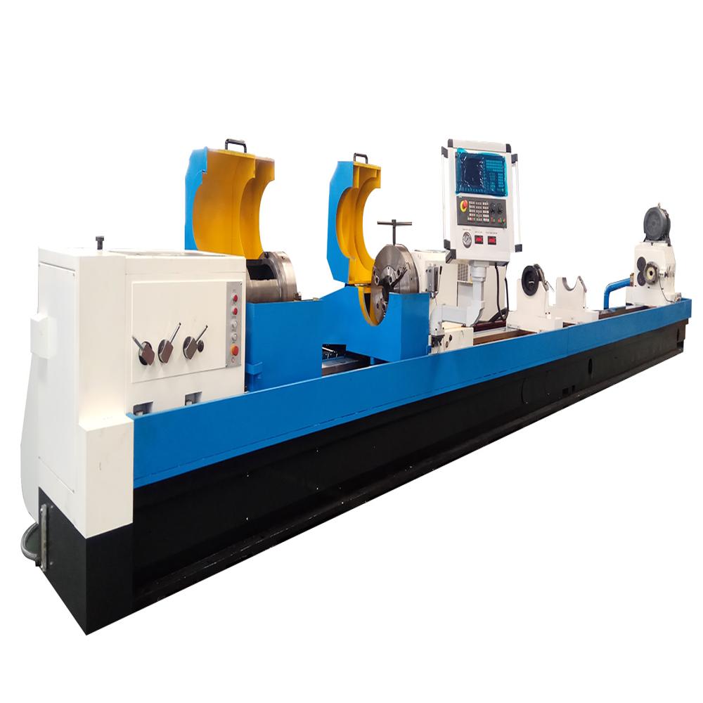
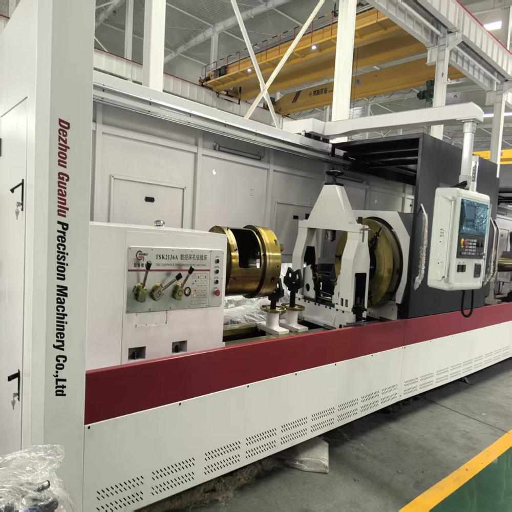
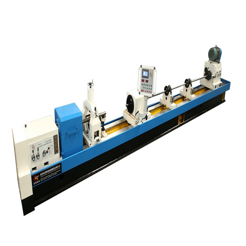
About BTA blind hole drilling and boring machine
Machine main structure:
Main parts of machineMachine bed, headstock , oil pressure head, drill bar support rest , drill box , sliding guide rail , Rack and pinion, coolant system , control system , electric cabinet, workpiece carrier etc. .
Workpiece clampingThe manual three-jaw chuck on the headstock clamps one end of the workpiece, and the cone disc on oil pressure head automatically tightens the other end of the workpiece.
Workpiece clamping sketch
Machine control system Control systemFANUC
- Z axis The longitudinal feed movement of the drill box, the servo motor drives the rack and pinion mechanism through the reducing mechanism.
- X axis: Oil pressure head servo tighten the workpiece , the servo motor drives the rack and pinion mechanism through the reducing mechanism.
- Install an industrial screen on the machine tool, and the operator can perform real-time operation and monitoring of the machine tool on the industrial screen.
- It can set the speed, feed rate, and processing depth, and can be infinitely adjusted during the processing, especially suitable for difficult to machine materials such as titanium alloys, stainless steel, and high-temperature alloys.
- Simultaneously equipped with multiple monitoring and alarm displays, it can digitally display the flow rate, pressure, liquid level, and oil temperature of the cooling system.
- The operation interface is simple and easy to understand, easy to get started, and convenient to operate.
The machine bed , box body, carriage etc. basic parts are precisely cast by super casting iron, processed by twice aging treatment after casting ,to eliminate stress , stable the structure and size , improve the mechanical properties ,etc. .
Machine bed
- The machine bed is made of resin sand and normalised after casting. The bed adopts split structure, assembled with high strength bolts and positioned by cone pin.
- Adopt double rectangular sliding guide rail, precision grinding, the guide rail surface is with high quenching hardness .
- The helical rack which is treated by precision processing and quenching is mounted inside of machine bed ,used for cutting tool feeding transmission . The machine has large bearing capacity, good rigidity and stable transmission.The V-shaped slant reinforced ribs are distributed inside of the machine bed ,
- supporting strength is high, and it is not easy to deform; The outer wall of machine bed support the guide rail directly, so the guide rail could bear large cutting force, with good rigidity, not easy to deform and vibrate during machining, it is good for improving the processing quality and working efficiency of machine .
- The oil returning slot mounted with oil shield is cast around the machine bed , so that the cutting oil on machine bed will return the coolant tank automatically .
Headstock :
- Used to drive the workpiece to rotate, fixed on the left end of machine bed .
- Manual three-gears , speed stepless within gear , the servo spindle motor drives the spindle to rotate through belt and gear box , the manual three-jaw chuck is installed in front of headstock for clamping the workpiece .
- The gears are machined by precision grinding , gear surface is quenched by high frequency quenching, so that the gears can obtain high strength, high hardness, high wear resistance and high fatigue limit, and can withstand relatively large alternating load and shock load.
- The external lubrication oil tank is used for circulating lubrication of gears and bearings, and a low liquid level alarm device is installed inside the oil tank.
- Install a button board on the headstock, which has functions such as spindle jog, feed forward, feed backward, and emergency stop.
Headstock Appearance
Oil pressure head
- Used for guiding the cutting tool, supplying cutting oil and supporting the drill bar .
- Servo motor drives its axial movement to adapt the workpiece with different length, and to tighten and loosen the workpiece .The servo motor can work under torque mode or position mode .
- The rotary bearings of oil pressure head are installed inside of the oil pressure head box, with good rigidity and high rotation accuracy .
- The rotary seal is installed on the outside of the right end of the oil pressure head body for easy maintenance.
- The drill bar support sleeve in installed on the right end of oil pressure head for supporting the drill bar .
- The guide sleeve ,cone disc and oil shield are installed on left end of oil pressure head , cone disc is used for positioning the workpiece, and guide sleeve is for guiding the direction of cutting tool .
- The oil shield is push-pull structure,the oil retention is mounted under the oil shield ,so that the cutting oil can return the oil tank .
- Oil pressure head appearance sketch
Drill box
- Used to drive the cutting tool to rotate, installed on the feeding carriage .
- Manual three-gears , speed stepless within gear , the servo spindle motor drives the spindle to rotate through belt,belt pulley and gear box .
- The tool shank connection sleeve at left end of spindle for clamping the cutting tool.
- The chips removal bucket is installed at the right end of spindle for discharging the cutting chips .
- The gears are machined by precision grinding , gear surface is quenched by high frequency quenching, so that the gears can obtain high strength, high hardness, high wear resistance and high fatigue limit, and can withstand relatively large alternating load and shock load.
- The external lubrication oil tank is used for circulating lubrication of gears and bearings, and a low liquid level alarm device is installed inside the oil tank.
- Drill box appearance sketch
Drill bar support rest
- Used to support the drill bar ;
- Adopt a integrate structure with high rigidity , the support sleeve is mounted on it , which can absorb the impact, vibration, etc. generated during the processing.
- Install an automatic pullback mechanism. When returning the tool, the feeding carriage can automatically pull the drill bar support rest back to its initial position.
- Drill bar support rest appearance sketch
Coolant system :
- Mainly composed of Cooling pump,chips box,oil tank etc. ,to supply enough cutting oil for deep hole processing .
- Oil tank : The fuel tank is fully welded with high-quality steel plates.
- Install a retractable protective cover between the chips boxes on the oil tank to prevent debris from falling into the tank.
- The pressure, liquid level, oil temperature, and flow rate of cutting oil can be displayed digitally on the control station .
- Coolant system sketch
Feeding carriage
- Used for driving the cutting tool to move axially .
- Lubricate the sliding guide surface timely and quantitatively with an auto lubrication station .
- The button board is mounted on the carriage ,which has functions of drill box spindle jog, feeding forward, feeding backward, emergency stop.
Lubrication system
- The sliding guide rail surface of the feeding carriage adopts automatic lubrication station for timed and quantitative lubrication, with a low liquid level alarm function .
- The bearings and gears of the headstock are circulating lubricated by an independent external oil tank, and have a low liquid level alarm function.
- The bearings and gears of the drill box are circulating lubricated by an independent external oil tank, and have a low liquid level alarm function.
- The oil pressure head carriage, drill bar support rest carriage are lubricated by manual lubricating pump .
Workpiece carrier
- Used for workpiece pre-positioning .
- The operator places the workpiece on the workpiece carrier first, and after the workpiece is clamped and positioned, the workpiece separate with the carrier.
- The V-shaped frame on the workpiece carrier is manually lifted and lowered using a T-shaped screw.
- Workpiece carrier sketch
Center frame
- Used to support workpieces; Three point closed center frame structure, with two rollers at the bottom and one roller at the top; The two rollers below adjust their lateral position through a screw.
- Center frame sketch
Superior Construction & Versatility
Constructed from cast iron for maximum durability, the BTA blind hole drilling and boring machine is ideal for a variety of industrial applications. Its automatic operation provides consistent accuracy, while the customizable voltage options allow seamless integration into different facility setups. The multicolor paint coating not only enhances appearance but also protects the machine from corrosion, ensuring a longer service life.
Customizable Operation & Comprehensive Support
This machine is tailored to meet customer voltage requirements, making it suitable for diverse industrial environments around the world. With an included warranty and support from experienced exporters and service providers, users receive reliable technical assistance, ensuring smooth operation from installation to maintenance.
FAQs of BTA blind hole drilling and boring machine:
Q: How does the BTA blind hole drilling and boring machine support industrial operations?
A: This machine offers precise drilling and boring capabilities, facilitated by its automatic-grade functionality, sturdy cast iron construction, and reliable electric power source, making it ideal for intensive industrial processes.Q: What materials and construction features ensure the machines durability?
A: The machine is built with high-quality cast iron, which provides strength and resistance to wear. Its surface is protected by a multicolor paint coating that guards against corrosion and damage in demanding industrial settings.Q: When does the warranty period for the BTA machine begin and how long does it last?
A: The warranty is valid for 12 months starting from the date of installation, or alternatively, 13 months from the dispatch date, whichever comes first.Q: Where can the machine be installed and used?
A: Designed for industrial use, the machine can be installed in manufacturing plants, fabrication workshops, and service facilities. It is suitable for numerous applications, including metalworking and precision engineering.Q: What is the process for customizing the machines voltage requirements?
A: Customers can specify their preferred voltage at the time of order. The manufacturer then adapts the machine to meet these requirements, with options including 440 volts and other voltages for integration into global electrical systems.Q: How does the automatic grade enhance usage and efficiency?
A: Automatic operation ensures consistent results with minimal manual intervention, thereby increasing productivity, reducing error rates, and providing a smoother workflow for industrial users.Q: What are the main benefits of choosing this machine for your operations?
A: Choosing this machine results in high-quality performance, extended durability, customizable specifications, and reliable after-sales service, making it a versatile resource for exporters, suppliers, and producers in industrial sectors.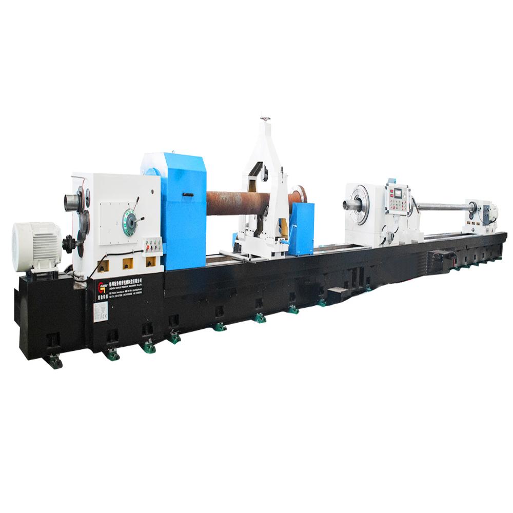
Tell us about your requirement

Price:
Quantity
Select Unit
- 50
- 100
- 200
- 250
- 500
- 1000+
Additional detail
Mobile number
Email

More Products in Bta Deep Hole Drilling Machines Category
BTA Drilling Machine for Tube Sheet
Price 1.0 USD ($) / Set
Minimum Order Quantity : 1 Set
Material : High Grade Steel Structure
Power Source : Electric
Automatic Grade : Automatic
Voltage : 380V/415V AC
Twin screw hole drilling machine
Price 46000.0 USD ($) / Set
Minimum Order Quantity : 1 Set
Material : casted iron
Power Source : Electric
Automatic Grade : Automatic
Voltage : Customer requirements Watt (w)
CNC Deep Hole Drilling & Boring Machine Series
Minimum Order Quantity : 1 Unit
Material : Highgrade Alloy Steel
Power Source : Electrical
Automatic Grade : Automatic
Voltage : 380415V, 3 Phase
BTA Deep Hole Drilling Machine
Price 60000.0 USD ($) / Set
Minimum Order Quantity : 1 Set
Material : Metal
Power Source : Electric
Automatic Grade : Automatic
Economic Development Zone,Dezhou - 253000, Shandong, China
Phone :86-534-15165964868
Email Id : dzguanlu@dzguanlu.com
|
 Send Inquiry
Developed and Managed by Infocom Network Private Limited.

